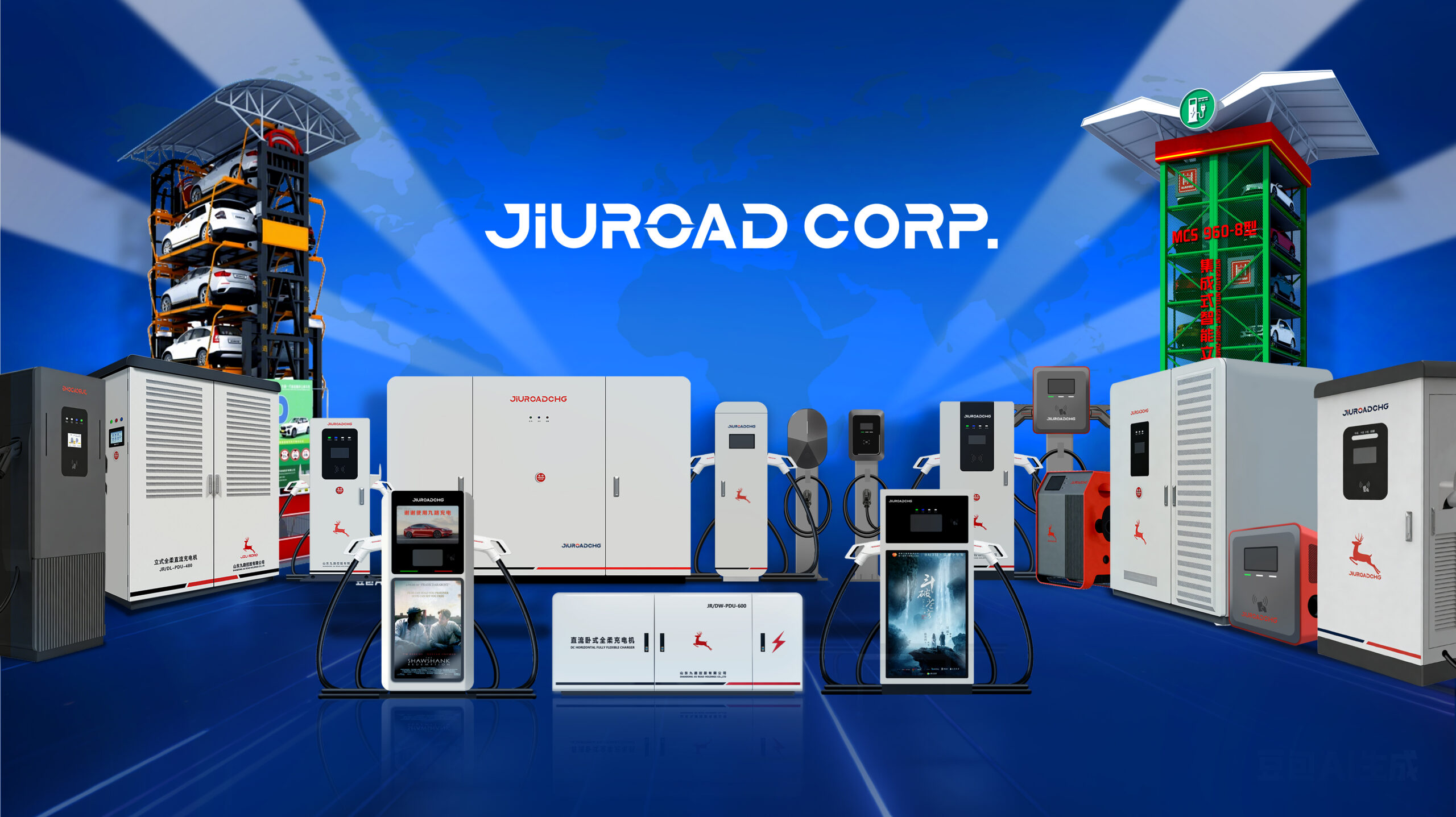
Modern fleet operators deploying 960KW charging systems face critical infrastructure gaps when interfacing with legacy electrical grids designed decades before electric vehicle adoption. Standard distribution transformers typically handle 300-500KW loads, creating immediate capacity constraints that trigger voltage drops and thermal overloads. These mismatches between contemporary charging demands and aging grid architecture require specialized substation configurations that incorporate load balancing protocols, advanced protection schemes, and smart switching technologies to prevent system failures during peak operational periods.
Key Takeaways
Legacy grids designed for 200-500KW loads require significant infrastructure upgrades to accommodate 960KW fleet charging demands.
High-voltage transformers stepping down 69kV-138kV to distribution levels are essential for heavy-duty fleet charging operations.
Microprocessor-based protection relays provide instantaneous fault detection and automated load-shedding to prevent cascading grid failures.
Substation capital costs range $150,000-$2.5 million but deliver 15-25% annual operational savings through demand charge optimization.
Compliance with IEEE 1547, NFPA 70E standards and utility interconnection requirements ensures safe grid integration.
Why Legacy Grids Struggle With 960KW Fleet Charging Demands
Most existing electrical distribution systems operate on infrastructure designed decades ago when peak commercial loads rarely exceeded 200-500KW per facility. These legacy grid challenges become pronounced when accommodating 960KW fleet charging operations, which demand nearly double the capacity of traditional commercial installations. Distribution transformers typically rated for 1-2MW must suddenly handle sustained high-power draws that approach their thermal limits. Voltage regulation systems struggle to maintain stable power quality under rapid load fluctuations inherent in fleet charging cycles. Charging capacity limitations emerge from outdated feeder cables, switchgear, and protection systems never engineered for sustained multi-megawatt operations. Service entrance equipment requires thorough upgrades to handle the substantial amperage increases, often necessitating utility-grade infrastructure modifications that extend beyond the facility’s property boundaries.
Essential Substation Components For Heavy-Duty Fleet Operations
Heavy-duty fleet charging substations require three critical component categories to handle multi-megawatt power demands safely and efficiently. High-voltage transformer systems form the backbone by stepping down transmission-level voltages to distribution levels suitable for fleet charging infrastructure. Advanced protection relay equipment and load management control units work in tandem to maintain system stability while preventing equipment damage during peak charging cycles that can exceed 10MW simultaneously across large fleet operations.
High-Voltage Transformer Systems
Transformers constitute the critical voltage conversion infrastructure within fleet substations, stepping down transmission-level voltages from 69kV to 138kV ranges to distribution levels of 4.16kV to 34.5kV suitable for fleet charging and maintenance operations. These power transformers must meet IEEE C57.12.00 standards while delivering transformer efficiency ratings exceeding 98.5% at full load to minimize operational losses during continuous heavy-duty operations.
Oil-immersed transformers with ONAN/ONAF cooling systems provide ideal thermal management for sustained 960KW loads. Critical specifications include impedance ratings between 5.75-7.5%, temperature rise limits per ANSI standards, and bushings rated for maximum system voltages. Thorough maintenance strategies incorporate dissolved gas analysis, thermal imaging, and annual electrical testing protocols to guarantee reliability and extend operational lifespan beyond 25-year design parameters.
Advanced Protection Relay Equipment
Microprocessor-based protection relays serve as the intelligent guardians of fleet substation electrical systems, providing instantaneous fault detection, isolation, and system coordination to prevent cascading failures during high-demand charging operations. These advanced systems incorporate relay technology advancements including adaptive protection algorithms, communication protocols, and real-time monitoring capabilities essential for 960KW operations.
Modern protection relay standards mandate thorough fault analysis and selective coordination to maintain power quality during simultaneous vehicle charging events. Critical specifications include:
- Differential Protection: Instantaneous detection of internal transformer faults with 1-2 millisecond response times
- Overcurrent Coordination: Time-current curve programming for selective fault isolation without affecting healthy circuits
- Communication Integration: DNP3 and IEC 61850 protocols enabling SCADA integration and remote monitoring capabilities
Load Management Control Units
Sophisticated load management control units orchestrate power distribution across multiple charging bays while maintaining electrical system stability under peak demand conditions exceeding 960KW capacity. These units integrate real-time monitoring systems with predictive algorithms to execute dynamic load balancing protocols. Advanced controllers utilize IEEE 2030.5 communication standards to coordinate with utility grid operators during high-demand periods.
Load forecasting capabilities enable proactive demand response strategies, preventing equipment overload while optimizing charging schedules across fleet operations. The control architecture incorporates automated load shedding mechanisms that prioritize critical charging requirements based on vehicle operational schedules. Energy efficiency optimization algorithms reduce peak demand charges through intelligent power factor correction and harmonic filtering. Redundant control pathways guarantee continuous operation during component failures, maintaining 99.9% system availability for mission-critical fleet charging infrastructure.
Power Transformer Specifications For Multi-Vehicle Charging Arrays
The electrical infrastructure supporting multi-vehicle charging arrays requires power transformers capable of handling substantial load variations while maintaining voltage stability across multiple charging points. Fleet operators must specify transformers with minimum 98% transformer efficiency ratings to reduce operational costs and thermal stress. The charging infrastructure demands three-phase pad-mounted transformers rated between 1500-2500 kVA to accommodate simultaneous heavy-duty vehicle charging without voltage sag.
Critical transformer specifications include:
- Harmonic mitigation capabilities – K-factor ratings of 9 or higher to handle non-linear loads from power electronics
- Temperature rise limitations – Maximum 65°C rise under full load conditions for extended operational lifespan
- Fault current coordination – Short-circuit withstand capability exceeding 25 times rated current for protective device coordination
IEEE C57.12.28 standards govern installation requirements for multi-vehicle charging applications.
Load Management Systems That Prevent Grid Overload
Load management systems serve as critical protective mechanisms that maintain grid stability during high-demand fleet charging operations through sophisticated control algorithms. These systems integrate dynamic power distribution controls, real-time grid monitoring capabilities, and automated load shedding protocols to prevent electrical infrastructure overload conditions. Implementation of these technologies guarantees compliance with IEEE 1547 interconnection standards while maintaining peak charging efficiency across multi-vehicle arrays.
Dynamic Power Distribution Controls
When fleet charging operations scale beyond a few dozen vehicles, dynamic power distribution controls become essential infrastructure components that actively monitor electrical demand and automatically redistribute power to prevent grid overload conditions. These systems employ dynamic load forecasting algorithms that analyze historical usage patterns, weather data, and vehicle scheduling to predict power requirements up to 48 hours in advance. Smart grid integration enables real-time communication between fleet substations and utility operators, facilitating coordinated demand response protocols.
Key operational parameters include:
- Load balancing algorithms that distribute 960KW capacity across multiple charging stations based on priority scheduling and grid availability
- Automated demand curtailment systems that reduce charging rates during peak utility periods without disrupting fleet operations
- Predictive maintenance protocols that monitor transformer temperatures, voltage harmonics, and power factor corrections
Real-Time Grid Monitoring
Continuous monitoring of electrical grid parameters forms the cornerstone of effective load management systems, enabling fleet substations to detect and respond to potential overload conditions within milliseconds of their occurrence. Advanced sensor networks continuously track voltage fluctuations, frequency deviations, and power factor variations across distribution networks. Real time data analytics processes these measurements through sophisticated algorithms that identify anomalous patterns before they escalate into system failures.
Modern monitoring platforms integrate SCADA protocols with IEC 61850 communication standards, ensuring seamless data transmission between substations and control centers. Grid performance optimization algorithms automatically adjust load distribution when critical thresholds approach dangerous levels. Predictive analytics capabilities enable proactive load shedding strategies, preventing cascading failures while maintaining essential fleet charging operations during peak demand periods.
Automated Load Shedding Protocols
Intelligent algorithms orchestrate systematic power reduction sequences across fleet charging networks, implementing hierarchical disconnection strategies based on predetermined priority matrices and real-time grid stability assessments. These automated protocols evaluate voltage fluctuations, frequency deviations, and transformer loading conditions to execute precise load shedding operations within milliseconds of detection thresholds.
Advanced control systems integrate IEEE 1547 standards with utility-grade protection schemes, enabling selective equipment isolation while maintaining critical infrastructure operations. Load shedding protocols coordinate with existing SCADA networks through standardized communication protocols.
- Tiered Priority Classification – Emergency services, transit operations, and commercial fleets receive hierarchical protection levels during grid stress events
- Dynamic Threshold Adjustment – Real-time recalibration of trigger points based on seasonal demand patterns and grid capacity
- Cascading Prevention Logic – Distributed load reduction prevents system-wide failures through coordinated regional response mechanisms
Voltage Regulation Technologies For Consistent Fleet Performance
As electric vehicle fleets scale to accommodate hundreds or thousands of units across diverse operational territories, maintaining precise voltage regulation becomes critical for guaranteeing uniform charging performance and battery longevity. Advanced automatic voltage regulators (AVRs) integrated with static VAR compensators provide real-time voltage stability across fluctuating load conditions. These systems maintain ±2% voltage tolerance through continuous monitoring and instantaneous correction mechanisms.
Power quality enhancement requires tap-changing transformers with load tap changers (LTCs) operating within 32-step regulation ranges. Capacitor banks with harmonic filters mitigate voltage distortion from non-linear charging loads. Digital voltage regulators employing microprocessor-based controls guarantee consistent 480V three-phase delivery regardless of grid variations. IEEE 519 compliance standards mandate total harmonic distortion below 5% for peak fleet charging infrastructure performance and equipment protection.
Fault Protection Protocols That Safeguard Both Fleet And Community Power
Fleet substations require extensive fault protection systems that respond within milliseconds to prevent cascading failures across interconnected power networks. Differential relay systems provide the primary defense mechanism by continuously monitoring current flow differentials and instantly isolating faulted equipment when abnormal conditions exceed predetermined thresholds. Grid isolation mechanisms serve as secondary protection layers, automatically disconnecting fleet operations from utility infrastructure to maintain community power continuity during internal fault conditions.
Differential Relay Systems
Multiple differential relay configurations form the backbone of fault protection systems within fleet substations, providing instantaneous isolation of internal faults while maintaining selective coordination with upstream and downstream protective devices. These differential relay types operate on current comparison principles, detecting internal transformer and bus faults within milliseconds. Relay system integration guarantees seamless communication between protection zones, preventing cascading failures that could compromise both fleet charging operations and community grid stability.
Key differential relay configurations include:
- Transformer differential protection – Monitors primary and secondary currents using percentage restraint characteristics per IEEE C37.91 standards
- Bus differential systems – Provides zone protection for switchgear assemblies with fiber-optic communication links
- Line differential relays – Coordinate with utility protection schemes through directional overcurrent elements and transfer trip schemes
Grid Isolation Mechanisms
Beyond differential relay protection, grid isolation mechanisms establish multi-layered fault protection protocols that automatically segregate fleet charging infrastructure from community distribution networks during abnormal operating conditions. These systems employ real-time grid monitoring through synchronized phasor measurement units that detect voltage deviations, frequency excursions, and harmonic distortions within millisecond timeframes. Advanced isolation techniques include motorized disconnect switches, vacuum circuit breakers, and solid-state transfer switches configured per IEEE 1547 standards. The protection scheme coordinates with utility SCADA systems to execute seamless islanding procedures during fault conditions. Primary isolation occurs at 12.47kV distribution levels, while secondary protection operates at 480V service entrance points. Transfer times comply with UL 1741 requirements, ensuring sub-cycle disconnection capabilities that protect both fleet operations and community electrical infrastructure integrity.
Demand Response Integration For Peak Load Optimization
Integrating demand response capabilities into fleet substation designs enables automated load curtailment during peak demand periods, reducing strain on transmission infrastructure and minimizing operational costs. Advanced demand forecasting algorithms analyze historical usage patterns and real-time grid conditions to predict peak events with 95% accuracy. Peak shaving protocols automatically defer non-critical charging operations to off-peak hours, maintaining fleet readiness while optimizing grid stability.
- Real-time load balancing systems continuously monitor grid frequency and voltage parameters, triggering immediate load shedding when utility signals indicate capacity constraints or emergency conditions.
- Dynamic pricing integration automatically adjusts charging schedules based on time-of-use tariffs and demand charges, achieving 15-25% operational cost reductions through strategic load shifting.
- Grid services participation enables substations to provide ancillary services including frequency regulation and spinning reserves, generating additional revenue streams.
Scalable Design Principles For Growing Fleet Operations
Fleet expansion requires substation architectures that accommodate growth without requiring complete infrastructure overhauls. Modular transformer configurations enable capacity increases from 960KW to multi-megawatt installations through standardized connection points and switchgear arrangements. Flexible infrastructure design incorporates expandable bus structures, allowing additional feeder circuits and load centers as fleet size increases.
Future proofing investments demands standardized voltage levels, conduit sizing at 125% of initial requirements, and pre-engineered connection points for additional transformers. Scalable protection schemes utilize digitally-configurable relays supporting multiple operating scenarios without hardware modifications. Space allocation follows IEEE C57.12.00 guidelines, reserving 40% additional footprint for equipment expansion. Load forecasting algorithms integrate fleet growth projections with utility coordination requirements, ensuring seamless capacity adaptations while maintaining N-1 redundancy standards throughout expansion phases.
Installation Requirements And Utility Coordination Strategies
While scalable infrastructure provides the foundation for fleet growth, successful substation deployment hinges on meticulous coordination between electrical contractors, utility providers, and regulatory authorities throughout the installation process.
Installation logistics require thorough site preparation, including soil analysis for foundation requirements, equipment staging areas, and maintenance access corridors. Critical path scheduling must account for utility engagement timelines, which typically extend 6-12 months for high-capacity connections exceeding 500KW.
Essential coordination strategies include:
- Pre-installation utility assessments – Load impact studies and grid capacity analysis determine interconnection feasibility and required infrastructure upgrades
- Permit synchronization protocols – Coordinated submission of electrical, building, and environmental permits prevents regulatory delays and expedites approval processes
- Commissioning verification procedures – Multi-party testing protocols ensure compliance with IEEE standards and utility interconnection requirements before energization
Cost Analysis: Substation Investment Vs Operational Savings
Substation capital expenditures typically range from $150,000 to $2.5 million depending on capacity requirements, with 1MW installations averaging $800 per kW including transformer banks, switchgear, and protective relay systems. Investment efficiency calculations must account for operational cost reductions through reduced demand charges, improved power factor correction, and elimination of utility upgrade fees. Fleet operators achieve long term savings averaging 15-25% annually through demand charge mitigation, which typically ranges $10-20 per kW monthly. Additional operational benefits include reduced transformer losses, improved voltage regulation, and enhanced system reliability. Payback periods generally span 3-7 years depending on local utility rate structures and fleet utilization patterns. Engineering studies demonstrate that properly sized substations deliver measurable ROI through combined infrastructure cost avoidance and operational efficiency gains.
Compliance Standards And Safety Certifications For Fleet Substations
Beyond the financial considerations of substation deployment, regulatory frameworks mandate adherence to multiple overlapping safety and performance standards. Fleet substations operating at 960KW capacity must satisfy IEEE 1547 interconnection requirements, NEMA enclosure ratings, and local utility interconnection agreements. Safety protocols encompass arc flash protection, grounding systems, and fault current coordination with existing grid infrastructure.
Critical compliance areas include:
- Electrical Safety Standards: NFPA 70E workplace safety requirements and OSHA 1910.269 power generation regulations govern personnel protection protocols
- Equipment Certification: UL 1741 inverter listings and IEEE C57.12.28 transformer standards guarantee component reliability under high-power operations
- Grid Integration Compliance: NERC reliability standards and regional transmission organization requirements maintain system stability during interconnection events
Documentation packages must demonstrate full regulatory compliance before commissioning authorization.
Conclusion
Fleet substation deployment validates the theory that legacy grid compatibility remains achievable through systematic infrastructure upgrades. Analysis demonstrates that 960KW operations integrate successfully when implementing proper transformer specifications, advanced protection systems, and dynamic load management protocols. Cost-benefit data confirms ROI realization within 3-5 years through operational efficiency gains. Compliance with IEEE 1547 and UL standards guarantees safety certification while maintaining grid stability. Strategic utility coordination proves essential for seamless integration and long-term operational reliability.